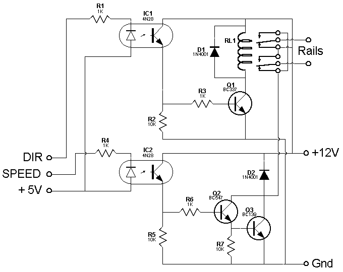
Block Control Interface
Circuit Diagram

Circuit Diagram in Postscript(46K)
Circuit Description
The direction and speed controls come from the I/O Extender. The +5V
connection goes to the interface as well. These signals go to opto-isolators
IC1 and IC2 respectively. When the direction signal is low, the transistor
in IC1 conducts and drives Q1. This activates the relay. On a change in
direction signal, Q1 turns off and deactivates the relay. The contacts
of the relay act like a reversing switch.
The speed signal drives the LED in IC2. This in turn drives the Darlington
pair Q2 and Q3. The output signal goes to the rails through the reversing
relay. Diodes D1 and D2 protect the transistors.


Updated on 23 Nov 95. Feedback to 


