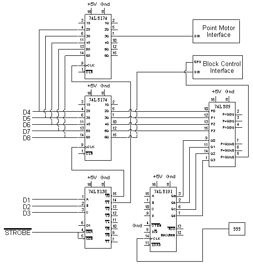
I/O Extender
This interface circuit connects to the parallel port of an IBM PC.
It expands the number of outputs up to 40. It also has the circuitry
to use 5 of these outputs to provide PWM speed control. Four of the
outputs are used to provide a speed value and one indicates the direction.
The speed value is translated to a PWM signal.
Circuit Diagram

Circuit Diagram in Postscript(49K)
Circuit Description
Three of the parallel port data pins provide a latch address which is
decoded by the 74LS138. The strobe from the port goes to... the strobe.
The decoder outputs a pulse on the appropriate line when a character
is written on the printer port. This pulse goes to a 74LS174 which
is connected to the other 5 data pins. The value on these pins is
latched. As the decoder has 8 outputs, up to 8 latches can be driven
giving a total of 40 possible outputs.
The PWM lines go to the P inputs of a 74LS85 comparator. The comparator
also has the output of a 74LS191 driven by a 555 timer going to the Q
inputs. The P>Q output provides the PWM speed signal. If the P input is
set to, say, 6, as the counter counts from 0 to F, the P>Q will be true
as the counter goes from 0 to 5. After that, it will be false as the
counter counts from 6 to F. Thus, the P>Q output remains active for
6 clock cycles out of 16. This is how the PWM signal is generated.
The 555 is set to oscillate at 1 KHz.
The direction signal of the speed controller and the point controller
signal do not need any logic and go directly to the interface. The
signals use LEDs so the signal controller lines do not even need
an interface.


Updated on 16 Nov 95. Feedback to 


