This system receives IR signals from existing remote controls and displays the waveform. It also attempts to categorize the signal based on several characteristics. The user can additionally interpret or tweak the parameters determined and store the information in a configuration file. This file will form the database of IR signals for any future applications.
An analysis of various IR signals using this system is presented in another section.
This project started as a way to send IR remote control signals from a PC to control hi-fi equipment, etc. A front-end program written in java will run on the PC and communicate with a PIC based circuit via the serial port. The PIC based circuit listens to commands on the serial port and sends out the IR signals.
In order to achieve this, a setup to analyse IR signals sent by existing remote controls is required. That is what this project is all about.
The main objective is to study the waveforms of various IR signals and gain a better understanding of them. It is also intended that a database of as many remotes be gathered and consolidated. This database can become the basis of future projects.
The PC provides the user interface and any complex logic. It also holds the repository of IR signal characteristics. The PIC deals with the sending and receiving of IR signals. The communication between the two is via a standard serial port.
The front-end on the PC is used to request the PIC circuit to sample an IR waveform and transmit its shape to the PC. The PC displays it and does some basic analysis to determine the characteristics of the signal. The user can additionally override or tweak this information and save it in a configuration file. The signal stored can be tested by using the front-end to send a command to the PIC circuit to transmit a given signal. This can be tested with the equipment that is supposed to respond to this signal.
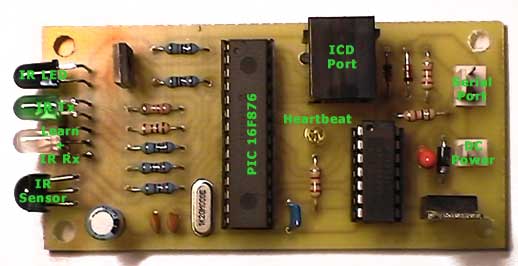
The circuit is built around a PIC16F876 running at 20MHz. This chip has a serial port and allows the use of an ICD - both characteristics make the development task easier. I have recently started using the ICD and find it very useful.
The output of the IR module drives one of the PIC inputs and a gate which indicates the presence of an IR signal using an LED. Two more LEDs are driven by the PIC - one to indicate Learn mode and the other acts as a heartbeat indicator. One PIC output drives a transistor that in turn drives an IR LED. This acts as the IR transmitter. An LED driven off the same output provides the visual indication of an IR transmission in progress. Two inverter gates are used to invert the output of the serial port These signals are sufficient to work with RS232 ports on most PCs.
You can download a PDF of the circuit diagram shown above.
I designed a PCB for this project. The artwork and legend can be downloaded. The original design had a DC power connector and the 9 pin D for the serial port mounted on the PCB. However, the case I was using did not have sufficient space for this. The case is an ABS enclosure measuring 120 x 60 x 30 mm from Jaycar. The PCB had to be large enough to use the mounting holes. This meant a PCB about 44 x 88 mm. There was plenty of space - so I put an RJ-11 connector as well to connect to the ICD without using the header board. This connection is very handy for debugging the system but cannot be used when the case is closed. The DC power connector is mounted on the side of the case and the 9 pin D is mounted at the back. All light sensors and LEDs are at one edge of the PCB - except for the heartbeat LED, which is not visible when the case is closed. The IR sensor may need to be optically screened from the other LEDs. One of the grey panels of the enclosure is replaced with a transparent panel. The unit uses a 9V wall wart.
Parts List
| IC1 | 16F876-20 | C1 | 100uF/12V | |
| IC2 | IS1U60 | C2 | 12pF | |
| IC3 | 74HC04 | C3 | 12pF/12V | |
| IC4 | 78L05 | R1 | 10K | |
| Q1 | BD139 | R2 | 1K | |
| D1 | LED | R3 | 10K | |
| D2 | IR LED | R4 | 1K | |
| D3 | LED | R5 | 1K | |
| D4 | 1N4148 | R6 | 100 | |
| D5 | 1N4148 | R7 | 10K | |
| D6 | LED | R8 | 220K | |
| X1 | 20 MHz crystal | R9 | 1K | |
| J1 | 2 pin SIL(DC Power) | |||
| J2 | 3 pin SIL(Serial Port) |
The assembly code listens to the serial port. On receiving a read command('R'), it samples the IR input at 5us intervals. As long as the state, high or low persists, a count is accumulated. The count is sent when the state changes or it reaches 127. The count is sent as a byte with the MSB set to the IR input corresponding to the count. For example, if the IR input was high for 220us, the byte output is 0xac, which is 44(the count) with the MSB set to 1(input was high for that period). If the IR input was low for 2200us, the bytes output are 0x3f, 0x3f, 0x3f, 0x3b. The byte stream is terminated by 0x00. If an error occurs a 0x80 is sent followed by a byte indicating the type of error. Errors that are sent currently are 0x41(no signal detected for 10 seconds approx.) and 0x42(timeout waiting for input change).
The periodic sampling is done by tweaking code so that the same number of cycles are used irrespective of program flow. I haven't done this before as I usually prefer an interrupt driven approach but the time period looked too small to take that approach. The serial port operates at 19.2K baud. It is good having a serial port instead of having to bit bang it.
The software is written in java and runs on a PC using the JRE 1.3. It uses the javax.comm libraries to access the serial port. There are two versions of the program - one is an application that allows capture, display and storage of waveform characteristics in an XML file and the other is an applet that displays the waveforms stored in the XML file. The front-end software has some modules that are common to both. One of the modules represents a large part of the UI of the application and almost all the UI for the applet.
The differences between IR signals is handled by putting all IR signal analysis and generation code into a Signal Analysis module. Each IR signal format for a manufacturer is handled by its own module. Some modules handle more than one manufacturer.
Each Signal Analysis module handles a range of functionality. They are listed below.
Manufacturers with signals that share the same characteristics but with different parameters are processed by the same module. The individual parameters are passed to the module to handle each manufacturer.
The applet version of the program is shown in the section on signal characteristics. It uses the same data file holding IR signal formats as the application program. It holds signal characteristics for each manufacturer and codes for various devices and functions in XML format.
The application looks similar to the applet. In addition, it has a menu bar and tool bar. It interacts with the PIC based circuit, communicating with it using the PC serial port.
To record the IR signals for a new remote, I write a new signal analysis module for that manufacturer code type. If I am lucky, an existing one can be used with a different set of signal parameters. One way to determine the signal coding type is to choose an arbitrary manufacturer and read the IR signal. The waveform is displayed. Drag the two hairlines to measure various parts of the signal. Once an analysis module is ready, I use the following steps.
The XML file now contains information on all tested buttons for that remote control. This can be used by the applet or application to regenerate the waveform for a device and function.
I started off using a Sharp GP1U52X module which I got a long time ago from a Tandy shop. This part is harder to find these days. However, newer units that are much more compact are now available(RS Electronics, Jaycar, Altronics, Farnell in Australia). I tried the Sharp IS1U60 available from RS Electronics for about AU$11. It tends to suffer from interference - from fluorescent lighting and from an LED indicator next to it. I will try buying a few different types and play around with it - I have heard good things about the Vishay TSOP1140.
I used my laptop to connect to the PIC circuit. I observed some bizarre behaviour by the circuit, which I attributed to the IR port on the laptop. It was probably sending out IR signals which were being received by the circuit. Optically screening the circuit from the laptop fixed the problem.
The carrier frequency of different remotes vary. The sensor is tuned to a particular frequency. The mismatch did not matter as the IR remote control was held close to the sensor. In applications where they are widely separated and the environment is less than ideal, this may be an issue.
The IR sensor is a crucial component. I started off using a Sharp GP1U52X that I bought from Tandy long ago. It is now difficult to obtain. Fortunately, better alternatives exist. I bought a ISU60 from R S Electronics for AU$11. Dick Smith(part no. Z1955), Jaycar(RPM7100 - part no. ZD1952) and Altronics(BRM1030 - part no. Z1611) have got something that looks similar costing AU$6.50 but I haven't tried them yet. These new sensors are much more compact than the old one.
You can download the PIC assembly code and the zipped up java source and jar executable. The java program does not incorporate all the described functionality yet.
A page on IR signal formats originally put together for an HP48 is still the best reference on the web for IR signals. Note that the bits in the codes I have listed are reversed in relation to this reference. This is probably because I treat the first bit received as the MSB. The ePanorama page on IR remote controls has lots of links to IR related pages and is also worth checking out.


